Credit for this method goes to Jay Couture. Credit for the writeup goes to @festerND-NaN.
You can watch the original calibration video for this method here:
http://www.youtube.com/watch?v=tDLbqLve128
This method will get you to within 0.1mm quickly, and can easily be used to get within 0.05mm with a few additional iterations. It consists of two parts; the first is your primary calibration routine, the next is an iterative method of calculating your arm radius.
Note: This was written assuming Smoothieware firmware. You will need to make some modifications to GCODE commands, or configuration file names for other firmware.
¶ Calculate gamma_max
This will insure that your trim setting will be a negative value, at the cost of a small amount of build height. (The build height that you lose has an exceptionally small diameter due to the weird delta build area, so no big loss.)
- Go to Home. (
G28) - Carefully step the nozzle down until you are
~1-2mmabove the build plate. - Find the current Z height. (
M114)
Set the gamma_max value in your config.txt to ~5mm less than the measured Z height from step 3.
¶ Finding Zero + Leveling
This is a recursive method. We start by calibrating the X axis, and then move on to calibrate Y and Z. Every time we make a change to one axis, we need to recalibrate the others. This is a little tedious, but once you get it down, you should be able to knock it out in about 5 minutes. (You should probably recalibrate before any large prints, or every 10 prints or so, depending on your printer.)
Note: It's entirely possible during this calibration that you will find two of your tower measurements oscillating between values. Because we're assuming .1mm is the smallest step size you move your nozzle, you could end up oscillating trim values by 0.1mm. In that case, you actually are .05mm off, and should try adding that to the trim, instead of the 0.1mm reported by M114.
¶ Finding 0.1mm above the bed
This calibration method relies on you being able to accurately find a position 0.1mm above your bed, at various locations. Our preferred method for doing this is as follows:
- Position your nozzle 5mm above the position you�re attempting to measure.
- Take a strip of standard paper, and start sliding it back and forth right below the nozzle.
- Manually jog the nozzle down
4mm, in1mmincrements. - Manually jog the nozzle down the rest of the way in
0.1mmincrements. - Once the nozzle grips the paper (it can no longer move back and forth), back up
0.1mm.
¶ Calibrate X Trim
Note: Trim offsets are always negative.
- Go to Home. (
G28) - Move to the base of your X tower. (
G1 X-86.6 Y-50 Z5) - Manually jog the nozzle down until it's
0.1mmabove the bed. (See above.) - Find the current Z height. (
M114) - Find the current trim offsets. (
M666) - Add the current Z height (from step 4) to the X trim value (from step 5). (
M666 X<value>)
ex:M114reportsZ: -1.4,M666reportsX:-4.2, so the new trim should be-5.6:M666 X-5.6 - Save the trim. (M500)
Repeat from step 1 until no more adjustments are necessary.
¶ Calibrate Y Trim
Note: Trim offsets are always negative.
- Go to Home. (
G28) - Move to the base of your Y tower. (
G1 X86.6 Y-50 Z5) - Repeat steps 3 through 8 of "Calibrate X Trim".
- Recalibrate X trim (starting at step 1).
Once X trim is calibrated, recalibrate Y trim (repeat from step 1) until no more adjustments are necessary.
¶ Calibrate Z Trim
Note: Trim offsets are always negative.
- Go to Home. (
G28) - Move to the base of your Z tower. (
G1 X0 Y100 Z5) - Repeat steps 3 through 8 of "Calibrate X Trim".
- Recalibrate X and Y trim (starting at step 1 of "Calibrate Y Trim").
Once X and Y trim is calibrated, recalibrate Z trim (repeat from step 1) until no more adjustments are necessary.
Save your calibration. (M500)
Congratulations, you have calibrated your towers!
¶ Calculating Arm Radius
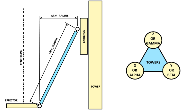
Visual representation of the part we're trying to measure.
- Trim X, Y, and Z first.
- Go to Home. (
G28) - Move to 0, 0, 5. (
G1 X0 Y0 Z5) - Manually jog the nozzle down until it's
0.1mmabove the bed. (See above.) - Find the current Z height. (
M114) - If Z is positive, reduce the radius (
M665 R<value>)If Z is negative, increase the radius (M665 R<value>) Note: The relationship between height and radius are non linear. (Most likely cos, sin, or tan.) We recommend you attempt to measure as closely as you can first, then using that number, try adjusting in0.2mmincrements. - Set your Z offset. (
M306 Z0). - Save your configuration. (
M500) - Recalculate trim on X, Y, Z.
- Repeat from step 1 until no more adjustments are needed.
- Save your configuration. (
M500)
Congratulations, you have calculated your arm radius!